TB 1-1520-238-20-66
(4) Inspect the micro switches for the following characteristics and record results only.
Torque strip on fastening hardware (mounting plate to SPAD Assembly.
Bent switch arms (roller arms).
Potting compound visible on one of the fasteners (nut/bolt) for the switch mounting
plate (mounting) plate to SPAD Assembly).
(5) Remove the SPAD Shear Pin for the SPAD Assembly (task 11.146, step b.). It is not
necessary to remove the Directional Push/Pull Rod. Inspect/retain the shear pin for later use.
(6) Allow the Mechanical Cam (spring loaded) to rotate, moving the roller-arms of the micro
switches activating (dosing) the switches (normally open contacts).
CAUTION
Use only 22 AWG electrical contact pins (MS27493-22D) to perform the
following continuity check. Do not use safety wire or facsimile, or damage
to the DASE Plugs may result (spread contacts).
(7) Pull (Open) the BUCS circuit breaker located on the Pilots center circuit
breaker panel.
(8) Gain access to the Aft Avionics Bay Door by opening door R295. Remove
connectors P688, P686 and P682 from the DASE Computer (7-211 D00005-21/23). Locate pin
66 on P682, insert a electrical pin. Locate pins 125 (51 ) and 126 (52) on P686 - insert electrical
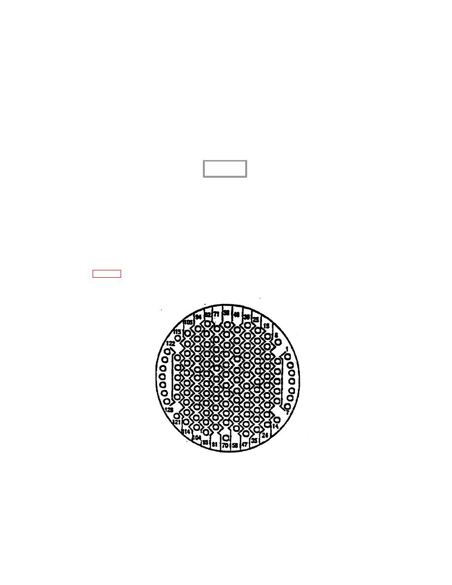
pins Reference figure 1 for depiction of these connector socket contacts, each connector has the
same contact pattern.
Figure 1. End View of DASE Connectors
P688, P686 and P682
4


 Previous Page
