
TB 1-1520-237-20-151
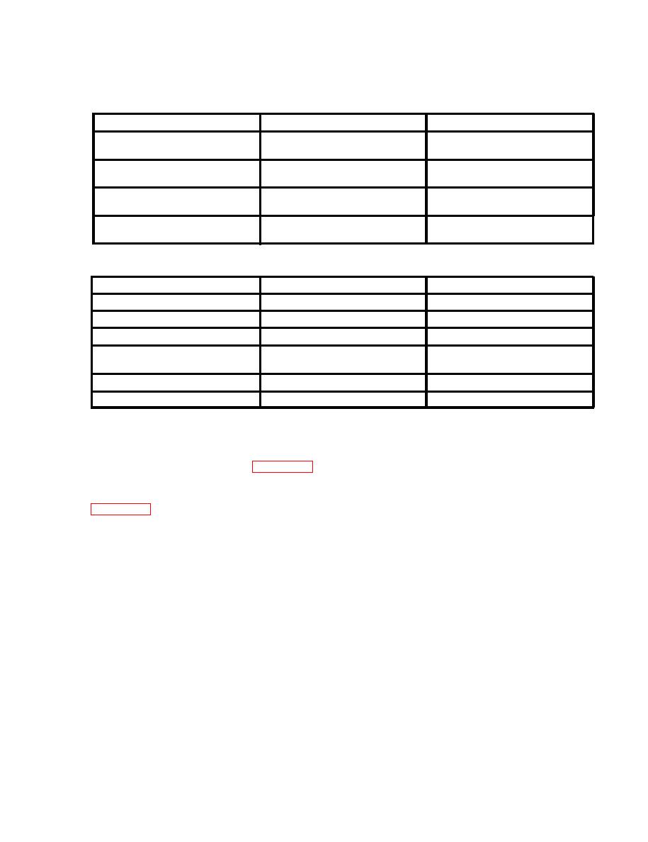
NATIONAL STOCK NUMBER
PART NUMBER
NOMENCLATURE
70070-10030-046
Main Rotor Spndl Assy
w/ Tie Rod
NNSN
70083-10001-045
Main Rotor Spndl Assy
w/ Tie Rod
NNSN
70070-10030-043
Main Rotor Spndl and
Liner Assy
NNSN
70070-10030-047
Main Rotor Spndl and
Liner Assy w/Tie Rod
7.
Parts to be Inspected.
NATIONAL STOCK NUMBER
PART NUMBER
NOMENCLATURE
70102-08216-041
Spindle and Liner Assy
3110-01-087-4101
SB7002-046
Bearing, Thrust, Elastomeric
Bearing, Thrust, Elastomeric
SB7002-048
3110-01-158-9607
840-80-9597
3110-01-220-7221
Bearing, Thrust, Elastomeric
(S/N C-325-00001 -02408)
70102-08100-044
Bearing Assy, Spindle
70102-08100-056
Bearing Assy, Spindle
8. Inspection Procedures.
a. Spindle Assembly. Review aircraft records to determine which spindle assembly is installed. If P/N
70102-08200-055 or later spindle is installed, no further action is required. If any other spindle is installed,
then perform corrective actions in paragraph 9a.
b. Elastomeric Thrust Bearing. Annotate aircraft record that inspection is due at the next PMS-2 in-
spection, to determine which elastomeric thrust bearing is installed. The inspection is to be conducted per
9. Correction Procedures.
a. At the next PMS-2 inspection, remove all identified part number (-054 and prior) spindle assemblies
and return to depot for corrective action. Again, if P/N 70102-08200-055 or later spindle is installed, no fur-
ther action is required for the spindle assembly. If a -054 or previous spindle is received from stock, it may
be utilized until the next PMS-2 inspection. At that time it is to be removed and returned to depot for corrective
action.
b. Repair/Replacement Procedures.
(1) Remove bearing assembly from aircraft and place on a suitable working surface. Visually
inspect the thrust bearing to determine which part number is installed. If P/N B40-80-9597 S/N sequence
C325-00001 through C325-02408 is found, thrust bearing must be replaced. If P/N LB5-1034-1-3 with S/N
sequence B325-XXXXX or P/N 840-80-9601, S/N C325-02409 or higher is found, inspection is complete.
(2) The following disassembly/maintenance procedures will be followed when separating the
thrust and spherical bearings after they have been removed from the aircraft and placed on a suitable working
surface:
(a) Remove the 8 each MS 21083N4 nuts, the 8 each MS20002C4 washers and 8 each NAS
1304 9H/NAS 6604-8/NAS 6604-H7 bolts.
(b) Separate the bearings and discard the 1 each 70102-08119-101 shim and shim
SS52C3000Z3237. if installed.
3

 Previous Page
