SB 742-1
or broken and the safety lever ears are properly assembled
under the lugs.
FRAGMENTATION GRENADES
c. If the grenade is upside down in the fiber container (fuze
is not visible), or if any of the above discrepancies are noted, it
a. FSC: 1330.
should remain inside the container and action taken to dispose
b. Ammunition Type: Grenade, Hand, Fragmentation, De- of it safely.
lay M26, M26A1, M33, M61, M67
c. Fragmentation hand grenades are used to supplement
a. Test of fuze assembly torque will be according to the ap-
small arms fire against the enemy in close combat. The gre- plicable portions of table R-2 and paragraph R-5b.
nade produces casualties by high velocity projection of
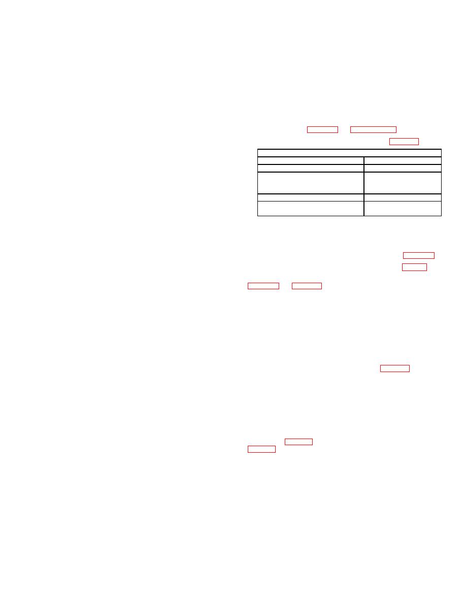
b. The required test equipment is listed in table R-1.
fragments.
d. Delay grenades, M26, M26A1, and M61 (G890/G880).
Description
Stock Number
Bodies are constructed of two pieces of thin wall sheet steel
and have a notched fragmentation coil liner. Bodies are filled
Fuze adapter, hand grenade
with Composition B. Each grenade is assembled with M204A1
Torque wrench, dial indicator, 50 As applicable
or M204A2 pyrotechnic delay detonating fuze. Difference be-
inch pound capacity direct reading
tween M26, M26A1 and M61 is that the M61 has a safety clip.
with memory indicator
Safety clip is designed to keep the safety lever in place should
Scribe, metal
As applicable
the safety pin be unintentionally removed from the grenade. It
Pitch-in Barricade, Hand Grenade, APE 1213M1
is an additional safety device used in conjunction with the
Delay Type
safety pin. The safety clip, of spring steel wire, consists of a
loop which fits around the fuze body and a clamp which fits R-4. Inspection category and sampling plan.
over the safety lever.
a. Inspection Category Y, periodic inspection interval --
three years.
e. Delay grenades, M33 and M67 (G888/G881). The gre-
nade body is a 2.5 inch steel sphere which is designed to burst
b. Sampling plan for inspection is according to chapter 2.
into numerous fragments when detonated. The grenade body
contains 6.5 ounces of high explosive, Composition B. Each
c. Inspection criteria for fuzes are contained in Appx S.
grenade is fitted with an M213 pyrotechnic delay detonating
d. Items will be inspected and classified according to
fuze. Difference between M33 and M67 is the M67 grenade
chapter 2 and table R-2.
has a safety clip.
f. Fuze, M204A1 and M204A2 (G877). These are pyrotech-
nic delay-detonating fuzes.
They differ only in body
a. Visually inspect the neck area for cracks. Cracks (usu-
construction. The body contains a primer and a pyrotechnic
ally in the seam area) that extend downward from the upper
delay column. Assembled to the body are a striker, striker
edge of the neck to the body and are completely through the
spring, safety lever, safety pin with pull ring, and a detonator
metal preclude proper torque being applied to the fuze. These
assembly. The split end of the safety pin has an angular
will be classified as major defects.
spread or diamond crimp.
b. Perform a test of fuze assembly torque according to the
g. Fuze, pyrotechnic delay detonating, M213 (G877).
following procedures:
(1) The body of the fuze contains a primer and a pyro-
(1) Equipment required is listed in table R-1.
technic delay column. Assembled to the body are a striker,
striker spring, safety lever, safety pin and pull ring, safety clip,
(2) Scribe a line across junction of fuze and grenade
and a detonator assembly.
body to provide means of detecting movement between compo-
nents. Apply 26 inch-pound torque in tightening direction
(2) The M213 fuze is equipped with a steel safety pin
(clockwise).
and pull ring. The split end of the safety pin is either spread
approximately 40 degrees or diamond shaped to prevent acci-
(3) Any movement of fuze at torque values of less than
dental removal and arming during shipping and handling. The 26 inch-pounds will be classified as a major defect. Otherwise
pull ring is provided to facilitate easy removal of the safety pin. serviceable lots rejected as a result of torque failure will be
assigned condition code E and reported by memorandum to
(3) A second safety feature is the steel safety clip. The
the office in para 1-5d(34) with information copy to the office in
safety clip's purpose is to prevent the safety lever from snap-
ping upward into a triggered position, in the event the safety
tained.
pin is accidentally dislodged from the fuze.
(4) Actual performance of test requires caution by op-
erator when applying torque to fuze body. Also avoid physical-
a. Grenades should never be lifted or handled by the ly contacting fuze lever while torquing, as inaccurate values
will result.
safety clip or the safety pin pull ring.
b. Before any grenade is removed from its fiber container, R-6. References:
it must be thoroughly inspected to see that the safety pin is in
a. TM 9-1300-200
place and undamaged and that the prongs of the safety pin are
b. TM 9-1330-200-12
spread approximately 45 degrees or diamond crimped. This
c. TM 9-1330-200-34
inspection must also ensure that the fuze lugs are not cracked
d. TM 43-0001-29
e. FM 23-30


 Previous Page
