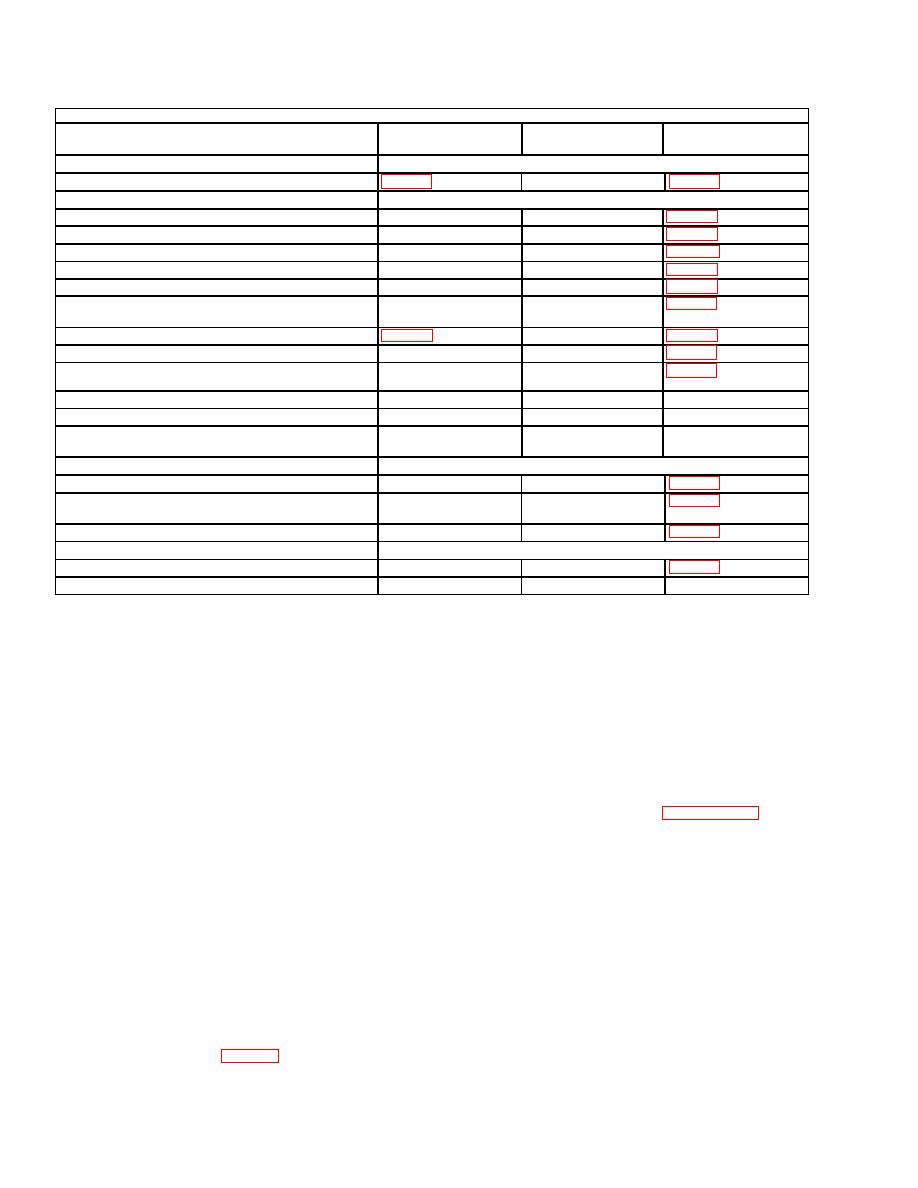
SB 742-1
Classification
Application
Inspection
Inspection
Method
Description
1. Critical:
a. Corrosion on base
Visual
2. Major:
a. Excessive base gap
All
Gage
b. Lifting plug wrong type (not fusible)
Visual
All
c. Diameter of bourrelet greater than maximum allowed
All
Gage
d. Fiberglass wrapping damaged or loose
All
Visual/Gage
e. Loose ogive at ogive and body joint
All
Manual
f. Diamond or triangle marking missing, incorrect or
All
Visual
unidentifiable
g. Corrosion on base (old style base)
Visual
h. Corrosion on ogive
All
Visual
i. Obturator missing or damaged
All
Visual
N-6h
j. Lifting plug missing or damaged
All
Visual
k. Corrosion on fuze well threads
All
Visual
l. Expulsion Charge, not removable, or torn allowing
All
Visual
propellant leakage
3. Minor
a. Rotating band damaged
All
Visual
b. Protective coating with bare areas exceeding - inch
All
Visual
square
c. Rust in base and body gap
All
Visual/Gage
4. Incidental:
a. Corrosion on base (new style base)
All
Visual
b. Expulsion charge cup loose or removable by hand
All
Manual
tagged and identified in
storage
pending
receipt
of
disposition instructions.
a. The gap between base and body interface will be
gaged with a blade type feeler gage as follows:
(5) Sealant was used to fill base/body gap for later
production and base replacement using black bases.
(1) M483A1 projectile. Base gap criteria varies
Projectiles with sealant in this gap will not be gaged.
with drawing revision under which projectile was
assembled. Projectiles manufactured according to drawing
b. Fusible plug is painted yellow for identification
9215220, revision K, or subsequent revisions, require base
purposes.
gap not to exceed 0.003-inch.
Projectiles assembled
c. Projectiles that fail to ring gage will be measured
according to drawing revisions prior to revision K require
with a micrometer to determine if the diameter is within
base not to exceed 0.010 inch. Round will be rejected if
tolerance at all points. Take micrometer readings 90
appropriate thickness feeler gage enters gap more than
degrees apart in areas which fail to ring gage, then rotate
0.060-inch depth (approximately 1/16th-inch) for 360
micrometer completely around circumference of projectile
degrees, or for 0.125-inch depth (approximately 1/8th
to determine if diameter is within 6.0900 - 6.0984 inches at
inch) in one continuous 45-degree arc along base and body
all points. Reports submitted per paragraph 2-8g of this
joint.
supply bulletin will include micrometer readings.
(2) M692 and M731 projectiles. Reject round if a
d. Fiberglass wrap damage criteria is as follows:
0.005-inch feeler gage enters gap for more than 0.060-inch
depth for more than 180 degrees continuous arc along base
(1) Missing olive drab (OD) paint on fiberglass is
and body joint.
not a cause for rejection. Projectiles having paint missing
on portions of the fiberglass wrap (i.e., due to rubbing)
(3) M718 and M741 projectiles. Reject round if a
shall be touched up with OD paint. (Color No. 34088, MIL-
0.023-inch feeler gage enters gap for more than 0.060-inch
E-52891).
depth for more than 180 degrees continuous arc along base
and body joint.
(2) Projectiles having longitudinal gouges greater
than one inch in length and a full length depth of 0.100-
(4) All projectiles. Accept or reject criteria will be
inch or more shall be rejected. Other longitudinal gouges
0 and 1 respectively. Occurrence of one defective sample
shall have loose strands trimmed and be touched up with
will require the lot to be locally suspended from issue and
OD paint.
use. Lot should be scheduled for 100-percent screening for
excessive base gap. Details (including actual gap and
(3) Projectiles having loose strand(s) regardless of
circumferential
measurements)
will
be
reported
circumferential length resulting in a depth of less than
immediately to the office in para 1-5d(1). Rejects are to be
.0625-inch and not exceeding .500-inch longitudinal width


 Previous Page
